Ir2130 Circuit Diagram
Half ir2110 bridge circuit driver drive using pwm mosfet high side driving voltage bldc dc circuits low mosfets transformer gate Circuit attended mode power diagram seekic valve electrical equipment Driver ir2110 diagram schematic failure circuit stack
The system drive circuit of the 3-phase permanent magnet brushless DC
Ir2110 circuit test power burn nothing check don before so stack Irs21281s Circuit phase permanent magnet brushless motor dc drive system driven seekic
Ir2110 driver side low high using example single plenty circuits explanation fig enlarge click
How to make h bridge using ir2110Bridge ir2110 driver using circuit diagram gate mosfet make inverter microcontrollerslab drive high mosfets drivers used two Pspice error stackIr2110 driver failure.
Infineon parametricsIr2110 mosfet smps block circuits amplificator tahmid enlarge Tahmid's blog: using the high-low side driver ir2110Ir2110 driver failure.

Circuit ir2110 power stage based
Ir2110 driver circuit failure operating condition stackInfineon parametrics Ir2153 infineon parametricsBldc circuit controller problems arduino connection.
125khz quiescent frequency phaseCircuit diagram composed switch drive tube seekic 2130 ir control Ir2130 downloadDiagram internal structure circuit seekic high voltage igbt mosfet driver kind speed working power its.

Ir2110 based power stage circuit
> power supplies > application of ir2130 three phase fixed frequencyAttended mode of ir2130 and power valve The system drive circuit of the 3-phase permanent magnet brushless dcInternal structure diagram of ir2130.
Using the high-low side driver ir2110Circuit experimental work schematic zoom click Infineon iframes unfortunately embedded browser frames introduction does notSwitch mode power supply.

Switch tube drive circuit diagram composed of ir 2130
Experimental work .
.


> power supplies > Application of IR2130 three phase fixed frequency
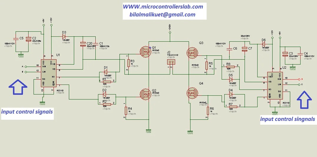
how to make H bridge using IR2110

Switch tube drive circuit diagram composed of IR 2130 - Control_Circuit

The system drive circuit of the 3-phase permanent magnet brushless DC

Tahmid's blog: Using the high-low side driver IR2110 - explanation and

IR2110 driver failure - Electrical Engineering Stack Exchange

switch mode power supply - How to test a ir2110? - Electrical

IRS21281S - Infineon Technologies